![<?echo $_SERVER['SERVER_NAME'];?>](/template/twentyseventeen/skin/images/header.jpg)
In the process of structural design, mold and processing, because different application software has its own system file format, in practical applications, different softwares are often used in combination with each other, and it is often used to look at 3D, NX. , Pro/e, Solidworks, etc. files are converted and reconverted. At present, all the common data exchange formats of CAD/CAM software include standard interface formats such as IGES, STEP and Parasolid, which are specially used to convert geometric data such as 3D surfaces, curves or points.
In theory, the surface constructed by Zhongwang 3D software belongs to the category of NURBS surfaces. NURBS surfaces generally have damaged surfaces, untrimmed surfaces or overlapping when transferred to another CAD/CAM software due to accuracy and other reasons. Problems such as surfaces. This article will show you how to fix a damaged surface problem after importing a 3D system.
First, the hybrid modeling technology of Zhongwang 3DZhongwang 3D uses the Overdrive core with its own intellectual property, which is characterized by hybrid modeling (the perfect interaction between solid modeling and surface modeling). The important feature is the non-regular shape modeling technology that supports wireframes, surfaces, and solid representations. NX's Parasolid kernel is a rigorous boundary representation solid modeling module that supports solid modeling, generalized unit modeling and integrated freeform surface/slice modeling. Parasolid has a strong styling function, but only supports regular solid modeling. The introduction of some complex shapes can result in data loss and broken faces; even for solids, some boundaries and surfaces are not available. Because of the core of the hybrid modeling technology, Zhongwang 3D uses the surface editing method to generate and delete the surface easily.
Second, Zhongwang 3D IGS / STEP file import and face repair1. Import of data conversion format
Zhongwang 3D imports the conversion data of any format into the system through the “Input†option under the “File†menu. When inputting, select the corresponding command according to the format of the input data. Define the target object as 3D data (parts) or 2D data (drawings and sketches), and then open the Set Options command dialog box to make input settings.
There is an "Automatic Stitching Geometry" command in the General Bar. Activate this option. If a closed area is formed between the surface and the surface, the system automatically stitches the model into one piece according to tolerances. Otherwise, the imported model will be a simple stack of separate surfaces (there are no common boundaries between the surfaces when the model is not shaded). This option is set to active by default, and the Force Close command automatically repairs the model to a solid within the tolerances.
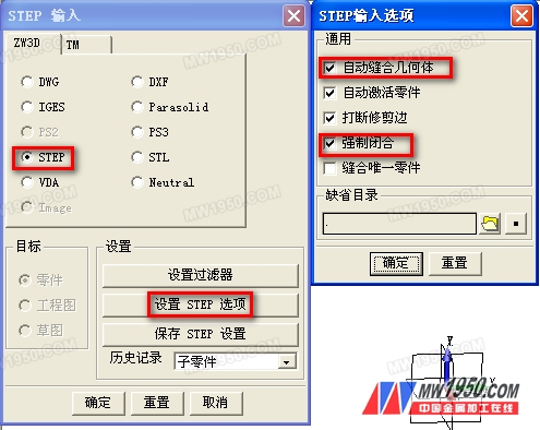
Enter the STEP data option settings
2. Check of data conversion results
After the setting of the above two command options, the data is smoothly imported. Check whether the imported data is complete or not by using the Show Open Boundary command in the Stitch toolbar. If the imported model is non-solid (there is a gap between the surface and the surface, the gap is displayed in blue in the drawing area). This command can pinpoint all open boundaries to facilitate data repair of the model.
Usually the model of the styling rule does not have gaps, and only the complex surface modeling is not rigorous due to the surface generation. After the data is converted, the gap is displayed. Users who are familiar with 3D software understand that when the original model data is scattered, the converted data will be seriously repaired into entities even in the subsequent work, which will seriously affect the user's work efficiency.
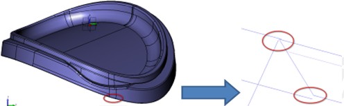
Scattered borders will hinder the development of follow-up work
3. Use the surface command to repair broken faces
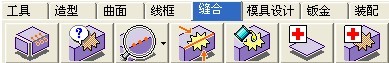
Stitch command toolbar
If there is a broken face in the imported shape, first use the "Check and delete tiny edges" function.  (The length is within the tolerance range) Remove the boundary formed by the tiny surface and optimize the shape. Then use the Analyze/Repair Part Topology feature
  Through this function, analyze and repair the boundary connection status.
There is a large surface gap and you can use the Surface Edit command in the Surface toolbar. Use the "delete ring" feature  Return the surface to the state it was in before cropping, then edit the shape with the Surface Crop command. Or use the "reverse ring" function
  Data recovery for the cropped surface.
Damaged surface data, repair can not achieve perfect results, you can directly use the "delete" function  , remove the surface, through the "sweep" function in the "model" toolbar
  And "stakeout" function
  Or use the Straight Face feature in the Surface toolbar
  And "U/V Surface" function
  , to rebuild the face.
Finally, the edited curved surface is stitched as a whole.  To make it an entity.
soap rack,soap holder,soap stand,stainless steel soap holder,steel wire soap stand,etc.Let your bathroom become more simple and upscale!Applicable to families, hotels, home stay and other places to use.
304 stainless steel never rust, will easy to clear, it's also very durable!
we are 15 year factory, we had big engineer team, and strong production line, can give you good serve and quanlity. Welcome to cooperation!
soap rack,soap stand,soap holder,soap dish,soap dish rack
Shenzhen Lanejoy Technology Co.,LTD , https://www.baking-rack.com