![<?echo $_SERVER['SERVER_NAME'];?>](/template/twentyseventeen/skin/images/header.jpg)
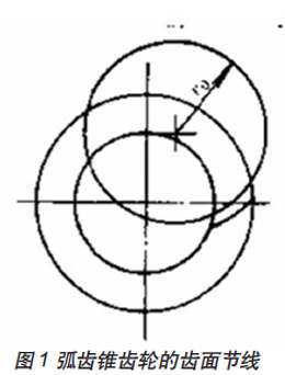
Spiral bevel gears are the key components of the main reducer of the drive axle of the automobile, and its quality accuracy directly determines the quality level of the entire bridge. Spiral bevel gears, imaginary face gear pitches of the workpiece are part of the arc. (figure 1)
Spiral bevel gear processing methods are many, including the exhibition method, forming method. Currently widely used is the exhibition method, which can be divided into single-single-number two-sided tooth cutting method, simple two-sided tooth cutting method, fixed installation tooth cutting method, single-single-number two-sided tooth cutting method and double-sided tooth cutting method.
According to the concept of an imaginary plane gear, we can use the trajectory of the cutter blade to replace the gear on the imaginary plane gear, and cut the bevel gear using the motion of the processed gear and the imaginary plane gear. To this end, the milling cutter disk is equivalent to the meshed gear.
The double-sided milling cutter disc, the average diameter Dg of the inner and outer tip, is called the nominal diameter of the milling cutter disc. The nominal diameter of a single-faced cutterhead is referred to by the nominal diameter of a double-faced cutterhead whose tip diameter is near.
The choice of the nominal diameter of the cutterhead is related to the size of the gear to be machined, the helix angle, the modulus, the relative position of the cone tip and the tip of the segment cone, and the cutting conditions. The correct choice of cutterhead diameter will directly affect the various gear parameters of the gear being processed, thus affecting the gear machining accuracy and machining efficiency.
Milling cutter wheel milling development analysis
In order to obtain a better tooth contact area, the small wheel is generally processed by an extrusion method. The relationship between the cutter head and the workpiece during machining is shown in Fig. 2.
It can be seen from the figure that the factors that mainly affect the position of the cutterhead are the midpoint cone pitch (average cone pitch A), the helix angle β, and the cutter radius Rc.
When adjusting the machine tool, the pitch cone surface of the gear to be cut must be tangent to the pitch cone surface of the imaginary flat-top gear, and pure rolling should be performed, and the optional cutter plane should be tangent to the cone of the gear being cut. Then the cutter head axis is perpendicular to the cone surface, and it is inclined with the pitch cone surface by an angle equal to the root angle of the gear being cut.
It can be seen from Fig. 3 that the cutter head is driven by the cradle of the machine tool, the center of the cradle is the center of the crown wheel, and the center of the machine tool coincides with the vertex of the pitch cone. The bend in the direction of the tooth length is a circle, and its radius is the same as the radius of the cutter head.
Analysis of Influence of Cutterhead Radius on Gear Tooth Curvature
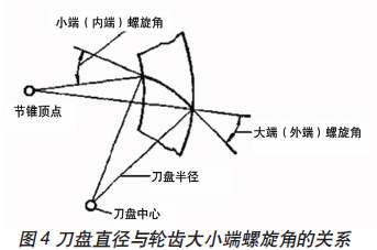
According to the concept of the spiral bevel gear, the helix angle is defined as the angle formed by the tooth surface pitch line and the pitch cone bus line passing through this point. From this, it can be seen that the spiral angle of each point in the tooth length direction of the spiral bevel gear is different. Although different cutter head diameter changes will not affect the midpoint helix angle, but in the case of a certain midpoint helix angle, the change in the cutter head diameter will cause the difference in the helix angle of the big end and the small end of the gear to change.
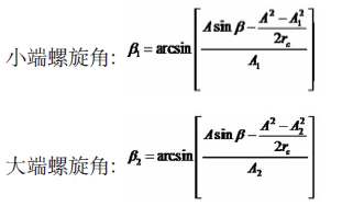
According to the gear design data, the helix angle calculation formulas for the size ends are:
Take a pair of gear pairs in China National Heavy Duty Truck Jinan Bridge Box Co., Ltd. as an example to illustrate the effect of selecting different cutter head radiuses:
The gear pair transmission ratio is 35/13, modulus is 13.2mm, shaft angle is 90°, pressure angle is 22.5°, tooth width is 72mm, midpoint helix angle is 35°, diameter of large circle is 462mm, diameter of small circle is 171.6mm. The outer cone is 246.42mm, the small cone is 174.42mm, and the midpoint cone is 210.42mm.
When using a cutter head with a nominal diameter of 20 inches: small end helix angle: 32°23'5â€, large end helix angle: 38°24'2â€, then the difference in helix angle between big end and small end is 6°57 ".
When using a cutter head with a nominal diameter of 18 inches: small end helix angle: 31°12'46â€, big end helix angle: 39°28'35â€, then the difference between the big end and the small end is 8°25 '49'.
When using a cutter head with a nominal diameter of 16 inches: small end helix angle: 29°46'49", big end helix angle: 40°50'40", then the difference between the big end and the small end helix angle is 11°3 '51'.
When using a cutter plate with a nominal diameter of 14 inches: small end helix angle: 27°56'46â€, big end helix angle: 42°38'1â€, the difference in helix angle between big end and small end is 14°41 '15'.
Although the change of the radius of the cutterhead has no obvious effect on the direct approach to the midpoint of the tooth surface, it has a significant effect on the change of the helix angle of the small end and the big end. Under the premise that the point helix angle is not changed, the closer the diameter of the selected cutter head is to the midpoint cone of the gear being processed, the smaller the spiral angle difference between the big end and the small end is.
The Effect of Milling Cutter Diameter on the Groove Width of the Small Wheel
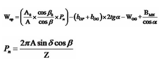
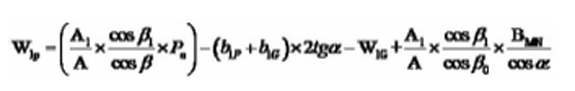
When the parameters of a pair of gear pairs are determined, the difference in the helix angle at both ends of the gear teeth is the main factor that determines the width of the teeth of the small gear. The calculation formula for the width of the small end tooth slot is:
Big wheel large end slot width:
The WOG is a large wheel with a large end slot width.
BMN is the largest normal minimum gap.
Pn is the midpoint normal week.
Big wheel large end slot width:
In the formula, b1P and b1G are the tooth root height of the small end of the small wheel and the tooth root height of the big end of the small wheel.
W1G is a large wheel small end slot width.
In the case that the large end-to-end slot widths are the same, we can analyze the influence of the cutter-plate diameter on the large-end slot width of the small-wheel gear.
From the formula in the previous section, it can be seen that the change of the diameter of the cutter plate directly affects the helix angle of the big end and the small end of the gear teeth. From the calculation formula of the large end slot width of the small wheel, it can be seen that the cutter radius is represented by the helix angle cosine of the first and fourth terms in the formula. The flank clearance in the fourth term in the formula is determined by the big end and is fixed, so it can be seen that the change in the first term has a greater influence on the tooth width of the small wheel.
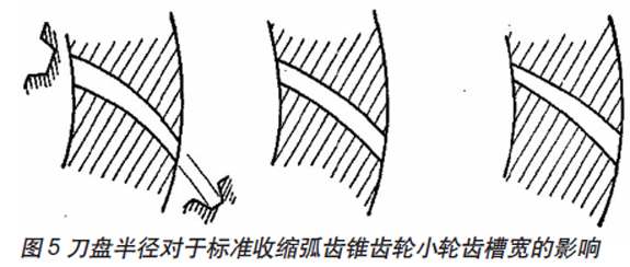
When considering the wear of precision cutting heads and the surface quality of tooth machining, the change of the finishing allowance at the big and small ends of the wheel is a key factor. In order to obtain a relatively uniform finishing allowance, the difference in the width of the small and large ends of the small wheel must be minimized.
From left to right, FIG. 5 is a schematic diagram of the effects of a small cutter radius, a standard cutter radius, and a larger cutter radius on the spline width of the jib. When a smaller cutter head is used, the width of the slot is reversely contracted, ie, the slot width at the small end of the gear tooth is greater than the slot width at the large end of the gear tooth. When a larger cutter head radius is used, the width of the small end tooth slots of the gear teeth will be too small, resulting in a very significant change in the margin during finishing.
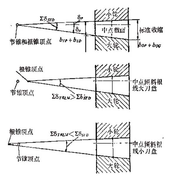
The Effect of Milling Cutter Diameter on the Gear Contraction of Inclined Root Line
The inclined root line (TRL) is the design of the Spiral bevel gear. It tilts the standard tooth line at a certain angle, making the teeth at the inner cone shorter and the teeth at the big end higher. Therefore, the width of the small end slot can be increased, and the width of the large end slot can be reduced accordingly. Therefore, the tooth root heights of both ends of the gear wheel are approximately the same to reduce the variation of the slot width.
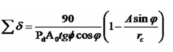
The sum of the sum of the radii of the big wheel and the small wheel of the oblique root line proposed by Wildhaber in 1945 is:
Pd is a radial section of the gear. In the root sloping mode, although the root line can be tilted around any section on the gear teeth, the most widely used is the root line around the tooth width midpoint section tilt (TRLM). When tilted along the midpoint of the tooth width, the required working tooth height is maintained at the midpoint of the tooth, while at the same time avoiding undercuts and tooth tip widths at both ends of the tooth being narrowed. When the radius of the cutterhead decreases, it also decreases. At that time, it is zero, that is, the case of a contour tooth.
Tilted root wire technology has the following advantages: It can reduce the shrinkage of the gear slot width using various cutter head radiuses. Because the choice of blade pitch is affected by the shrinkage of the slot width, the maximum blade pitch available is limited by the minimum slot width of the teeth, so the reduction of slot width shrinkage makes the selection range of blade pitch more convenient. Big.
Figure 6 shows the effect of the radius of the cutter head on the sum of the tooth root angles of the spiral bevel gears.
Conclusion:
The influence of various parameters of spiral bevel gear milling cutterhead on gear tooth geometry parameters and gear transmission strength is not widely used in China. Research and exploration are not thorough enough, and we need to further carry out relevant theoretical exploration and experimental research.
Spiral bevel gear processing methods are many, including the exhibition method, forming method. Currently widely used is the exhibition method, which can be divided into single-single-number two-sided tooth cutting method, simple two-sided tooth cutting method, fixed installation tooth cutting method, single-single-number two-sided tooth cutting method and double-sided tooth cutting method.
According to the concept of an imaginary plane gear, we can use the trajectory of the cutter blade to replace the gear on the imaginary plane gear, and cut the bevel gear using the motion of the processed gear and the imaginary plane gear. To this end, the milling cutter disk is equivalent to the meshed gear.
The double-sided milling cutter disc, the average diameter Dg of the inner and outer tip, is called the nominal diameter of the milling cutter disc. The nominal diameter of a single-faced cutterhead is referred to by the nominal diameter of a double-faced cutterhead whose tip diameter is near.
The choice of the nominal diameter of the cutterhead is related to the size of the gear to be machined, the helix angle, the modulus, the relative position of the cone tip and the tip of the segment cone, and the cutting conditions. The correct choice of cutterhead diameter will directly affect the various gear parameters of the gear being processed, thus affecting the gear machining accuracy and machining efficiency.
Milling cutter wheel milling development analysis
In order to obtain a better tooth contact area, the small wheel is generally processed by an extrusion method. The relationship between the cutter head and the workpiece during machining is shown in Fig. 2.

It can be seen from the figure that the factors that mainly affect the position of the cutterhead are the midpoint cone pitch (average cone pitch A), the helix angle β, and the cutter radius Rc.
When adjusting the machine tool, the pitch cone surface of the gear to be cut must be tangent to the pitch cone surface of the imaginary flat-top gear, and pure rolling should be performed, and the optional cutter plane should be tangent to the cone of the gear being cut. Then the cutter head axis is perpendicular to the cone surface, and it is inclined with the pitch cone surface by an angle equal to the root angle of the gear being cut.
It can be seen from Fig. 3 that the cutter head is driven by the cradle of the machine tool, the center of the cradle is the center of the crown wheel, and the center of the machine tool coincides with the vertex of the pitch cone. The bend in the direction of the tooth length is a circle, and its radius is the same as the radius of the cutter head.
Analysis of Influence of Cutterhead Radius on Gear Tooth Curvature
According to the concept of the spiral bevel gear, the helix angle is defined as the angle formed by the tooth surface pitch line and the pitch cone bus line passing through this point. From this, it can be seen that the spiral angle of each point in the tooth length direction of the spiral bevel gear is different. Although different cutter head diameter changes will not affect the midpoint helix angle, but in the case of a certain midpoint helix angle, the change in the cutter head diameter will cause the difference in the helix angle of the big end and the small end of the gear to change.
According to the gear design data, the helix angle calculation formulas for the size ends are:
Take a pair of gear pairs in China National Heavy Duty Truck Jinan Bridge Box Co., Ltd. as an example to illustrate the effect of selecting different cutter head radiuses:
The gear pair transmission ratio is 35/13, modulus is 13.2mm, shaft angle is 90°, pressure angle is 22.5°, tooth width is 72mm, midpoint helix angle is 35°, diameter of large circle is 462mm, diameter of small circle is 171.6mm. The outer cone is 246.42mm, the small cone is 174.42mm, and the midpoint cone is 210.42mm.
When using a cutter head with a nominal diameter of 20 inches: small end helix angle: 32°23'5â€, large end helix angle: 38°24'2â€, then the difference in helix angle between big end and small end is 6°57 ".
When using a cutter head with a nominal diameter of 18 inches: small end helix angle: 31°12'46â€, big end helix angle: 39°28'35â€, then the difference between the big end and the small end is 8°25 '49'.
When using a cutter head with a nominal diameter of 16 inches: small end helix angle: 29°46'49", big end helix angle: 40°50'40", then the difference between the big end and the small end helix angle is 11°3 '51'.
When using a cutter plate with a nominal diameter of 14 inches: small end helix angle: 27°56'46â€, big end helix angle: 42°38'1â€, the difference in helix angle between big end and small end is 14°41 '15'.
Although the change of the radius of the cutterhead has no obvious effect on the direct approach to the midpoint of the tooth surface, it has a significant effect on the change of the helix angle of the small end and the big end. Under the premise that the point helix angle is not changed, the closer the diameter of the selected cutter head is to the midpoint cone of the gear being processed, the smaller the spiral angle difference between the big end and the small end is.
The Effect of Milling Cutter Diameter on the Groove Width of the Small Wheel
When the parameters of a pair of gear pairs are determined, the difference in the helix angle at both ends of the gear teeth is the main factor that determines the width of the teeth of the small gear. The calculation formula for the width of the small end tooth slot is:
Big wheel large end slot width:
The WOG is a large wheel with a large end slot width.
BMN is the largest normal minimum gap.
Pn is the midpoint normal week.
Big wheel large end slot width:
In the formula, b1P and b1G are the tooth root height of the small end of the small wheel and the tooth root height of the big end of the small wheel.
W1G is a large wheel small end slot width.
In the case that the large end-to-end slot widths are the same, we can analyze the influence of the cutter-plate diameter on the large-end slot width of the small-wheel gear.
From the formula in the previous section, it can be seen that the change of the diameter of the cutter plate directly affects the helix angle of the big end and the small end of the gear teeth. From the calculation formula of the large end slot width of the small wheel, it can be seen that the cutter radius is represented by the helix angle cosine of the first and fourth terms in the formula. The flank clearance in the fourth term in the formula is determined by the big end and is fixed, so it can be seen that the change in the first term has a greater influence on the tooth width of the small wheel.
When considering the wear of precision cutting heads and the surface quality of tooth machining, the change of the finishing allowance at the big and small ends of the wheel is a key factor. In order to obtain a relatively uniform finishing allowance, the difference in the width of the small and large ends of the small wheel must be minimized.
From left to right, FIG. 5 is a schematic diagram of the effects of a small cutter radius, a standard cutter radius, and a larger cutter radius on the spline width of the jib. When a smaller cutter head is used, the width of the slot is reversely contracted, ie, the slot width at the small end of the gear tooth is greater than the slot width at the large end of the gear tooth. When a larger cutter head radius is used, the width of the small end tooth slots of the gear teeth will be too small, resulting in a very significant change in the margin during finishing.
The Effect of Milling Cutter Diameter on the Gear Contraction of Inclined Root Line
The inclined root line (TRL) is the design of the Spiral bevel gear. It tilts the standard tooth line at a certain angle, making the teeth at the inner cone shorter and the teeth at the big end higher. Therefore, the width of the small end slot can be increased, and the width of the large end slot can be reduced accordingly. Therefore, the tooth root heights of both ends of the gear wheel are approximately the same to reduce the variation of the slot width.
The sum of the sum of the radii of the big wheel and the small wheel of the oblique root line proposed by Wildhaber in 1945 is:
Pd is a radial section of the gear. In the root sloping mode, although the root line can be tilted around any section on the gear teeth, the most widely used is the root line around the tooth width midpoint section tilt (TRLM). When tilted along the midpoint of the tooth width, the required working tooth height is maintained at the midpoint of the tooth, while at the same time avoiding undercuts and tooth tip widths at both ends of the tooth being narrowed. When the radius of the cutterhead decreases, it also decreases. At that time, it is zero, that is, the case of a contour tooth.
Tilted root wire technology has the following advantages: It can reduce the shrinkage of the gear slot width using various cutter head radiuses. Because the choice of blade pitch is affected by the shrinkage of the slot width, the maximum blade pitch available is limited by the minimum slot width of the teeth, so the reduction of slot width shrinkage makes the selection range of blade pitch more convenient. Big.
Figure 6 shows the effect of the radius of the cutter head on the sum of the tooth root angles of the spiral bevel gears.
Conclusion:
The influence of various parameters of spiral bevel gear milling cutterhead on gear tooth geometry parameters and gear transmission strength is not widely used in China. Research and exploration are not thorough enough, and we need to further carry out relevant theoretical exploration and experimental research.
Instant Coffee Maker,Expressi Coffee Machine,Small Coffee Maker,Coffee Machines For Home
Ningbo DeNeu Imp. & Exp. Co., Ltd , https://www.deneucn.com