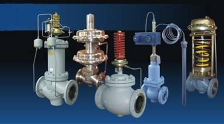
First, the definition of the control valve
Control device for regulating fluid flow in industrial process control systems
The control valve can also be called a regulating valve. It regulates fluid pressure, temperature, flow rate, liquid level and other process parameters by controlling fluid flow.
Second, the control valve application
Control valves can be used in chemical, petrochemical, electric power, oil and gas, metallurgy, pharmaceutical, paper, light industry, food, electronics and other industries. Control valves are important control components that affect the quality of control (control accuracy) and even product quality of industrial process control systems . The performance and control accuracy of the control valve directly affects the economic benefits of industrial production.
Control valves are often the weakest link in the control loop
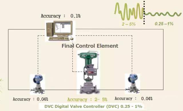
Third, the composition of the control valve
The control valve is mainly composed of two parts. Valve body assembly + actuator
4. Organizations related to common standards for control valves
(1) American National Standards Organization (ANSI)
(2) American Society of Mechanical Engineers (ASME)
(3) American Society for Testing and Materials (ASTM)
(4) American Petroleum Organization (API)
(5) International Society for Measurement and Control (ISA)
(6) International Organization for Standardization (ISO)
(7) International Electrotechnical Commission (IEC)
(8) International Society of Corrosion Engineers (NACE)
(9) Fluid Control Organization (FCI)
(10) Manufacturer Standardization Society (MSS)
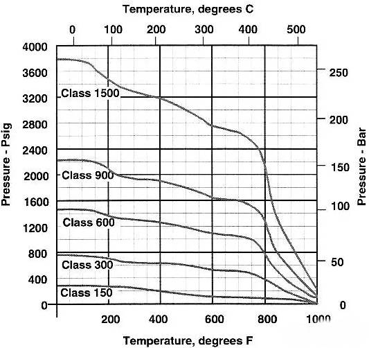
Five, the valve pressure capacity expression method has two
(1) Pressure rating (CL)
(2) Nominal pressure (PN)
The relationship between the International Organization for Standardization (ISO) released standard, pressure rating and nominal pressure: CL 150: PN 20 CL 900 : PN 150
CL 300 : PN 50 CL 1500 : PN 260
CL 600 : PN 110 CL 2500 : PN 420
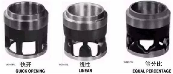
Sixth, the flow characteristics of the control valve
The flow characteristic of the control valve is the relationship between the stroke of the control valve in the range of 0-100% and the corresponding flow rate through the control valve .
The flow characteristics of the valve when the differential pressure is constant are referred to as the inherent flow characteristics.
The flow characteristics of the valve under conditions such as differential pressure are called actual flow characteristics.
1. There are three kinds of flow characteristics of the control valve.
(1) Fast opening flow characteristics;
(2) Linear flow characteristics;
(3) Equal percentage flow characteristics.
Seven, the main performance indicators of the control valve
(1) Adjustable ratio - The ratio of the maximum controllable flow of the control valve to the minimum controllable flow.
(2) Flow capacity - the flow through the valve under specified conditions.
(3) Air chamber sealing - the degree to which the actuator chamber pressure drops during a specific time at a specific pressure.
Eight, flow coefficient (Cv):
The flow coefficient refers to the water pressure of 40-60 €€ at a pressure drop of 1 PSI (pounds per square inch). The flow coefficient per minute of flow through the valve at a certain opening of the valve is indicative of the valve flow capacity. Parameters. The flow coefficient is related to the valve flow geometry, valve size, valve opening and other parameters. Basic formula for adjusting valve size: Q = Cv√△P / G
FISHER uses different symbols to represent different media flow coefficients. Cv--liquid Cg-gas Cs--steam
Using the International System of Units, the flow coefficient is expressed in Kv.
The flow coefficient KV refers to the number of cubic meters of water flowing through the valve per hour at a certain opening of water at a pressure of 100 kPa at a temperature of 5-40 °C . Cv and Kv conversion relationship: Cv = 1.167 Kv
Nine, the deviation of the control valve
a. Basic error
Ei = ( li- Li )/L X 100% Â Â Â Â Â Â Â Â Â Â Â
Ei - error at point i
Li - the actual itinerary of point I
Li - theoretical travel of the i-th point
L - rated stroke of the control valve
b. Hysteresis The maximum difference between the forward and reverse strokes measured on the same input signal
c. Dead zone (control valve)
The pressure interval that does not act on the actuator diaphragm is the difference between the positive and negative signals at a certain point on the control valve stroke.
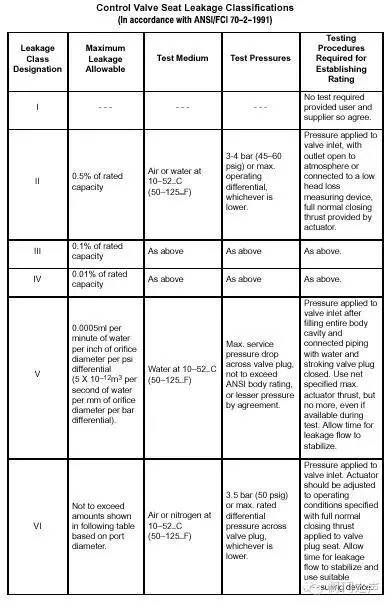
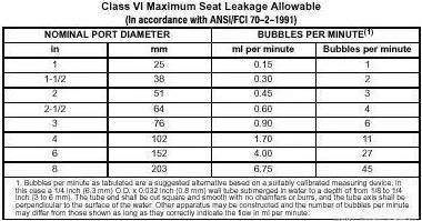
X. (Seat) leakage
The flow rate of the medium flowing through the valve when the valve is fully closed under certain pressure difference and temperature conditions. The amount of leakage is an indicator of the leakage inside the valve:
Close Level ANS II--VI
11. Common materials for internal parts
(1)416 SST
It is resistant to water and steam media and is commonly used in power plant water supply systems to manufacture valve seat. Due to high stress, no surfacing and surface hardening treatment, the hardness is lower when the working temperature is higher than 427 °C.
(2)17-4 PH
It has good corrosion resistance and high strength. It is often applied to 3 kinds of hardening treatments (H900, 1075, 1150) to manufacture cages, valve seats, valve plugs and valve shafts. It is brittle when the temperature is high, higher than 800 F ( 427 °C ) is forbidden.
(3)440 SST
The highest hardness control valve stainless steel material (HRC60), good corrosion resistance, the use temperature is not higher than 427 °C , such as power plant boiler feed valve. Mainly used to manufacture CAVITORL cages
(4) ALLOY 6
Even remains at a high temperature corrosion resistance and wear resistance superior performance, up to maintain good performance at 566 ℃ high temperature steam conditions. Mainly used for surfacing the valve seat. The cutting properties, castability is poor, and high cost, which is not used for producing the cage.
12. Common materials for valve body
WCC/WCB
High quality carbon steel (low carbon steel), low price, good weldability, low temperature and brittleness, low strength at high temperature (working temperature -29 °C - 427 °C )
WC9
Low-alloy chrome-molybdenum steel, suitable for >427 C superheated steam and severely scouring conditions, corrosion resistance is better than carbon steel, weldability is better than C5, thermal expansion performance, thermal conductivity is better than CF8M, working temperature -29 °C € 593 °C
13. Common treatment methods for valve parts:
(1) Coating treatment: the surface of the part is applied
a. Chrome layer (V-ball, butterfly disc, advanced processing technology can make the coating working temperature up to 590 °C and maintain good wear resistance)
b. Nickel layer (for example, ENC-Electroless Nickel Coating is often used for cage treatment, operating temperature is not higher than 340 °C )
Coating thickness: The nickel layer is usually about 0.05mm, and the chromium layer is usually about 0.01mm.
(2) Seepage treatment:
Chemical heat treatment, the thickness of the layer is about 0.05-0.10mm, which is often used for the hardening of the cage. The working temperature is up to 590 °C.
Fourteen, control valve classification
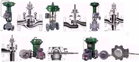
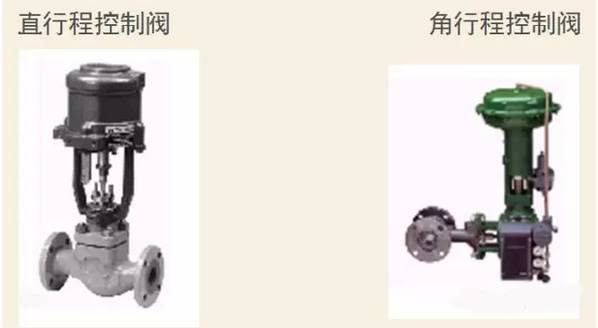
1. Classified by structure of control valve
Cage valve single seat valve double seat valve three way valve angle valve ball valve disc valve
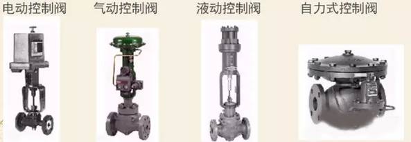
2. Classified by control method of control valve
3. Classified by the action mode of the control valve
Fifteen, control valve connection
(1) The connection form of the valve body and the pipe
There are three common ways to connect the valve body to the pipe:
(1) Threaded connection (2) Flange connection (3) Welding
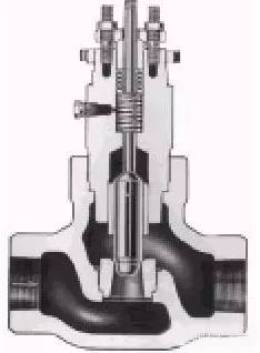
1. Threaded connection (below) Features:
a. Commonly used for small size valves (not more than 2 inches).
b. Lower cost than flanged joints.
c. Thread is usually pipe thread (NPT)
d. The lower line of the valve body is not as convenient as the flange connection
2. Features of flanged connection:
Suitable for a wide range of pressures for control valves up to 815 C. Available in a variety of sizes.
There are three common types of flanged connections:
a. flat (FF) flange
b. protruding surface (RF) flange
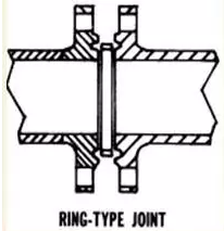
c. Ring (RTJ) flange
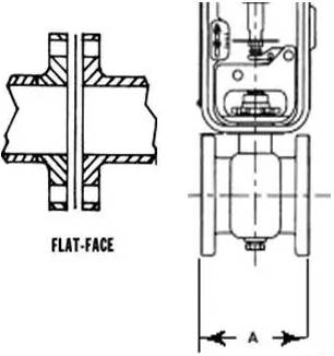
3. Features of the flat flange (below)
Commonly used in low pressure applications, cast iron valve body, copper valve body is often a flat flange.
The flange face is in full contact with the gasket, and the flange stress caused by the bolt fastening is low.
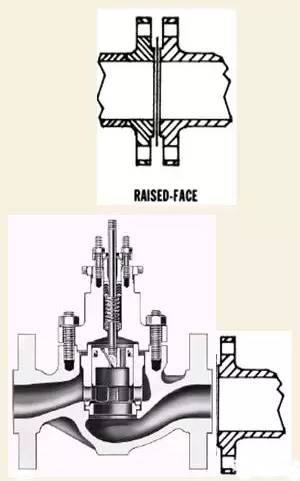
4. Features of the face flange (below):
The face is finished and has concentric grooves on the surface to ensure that the sealing flange can be used with gaskets of various materials. The working pressure can reach 414 kg/m2 (6000 psi) and the working temperature can reach 815. Degree (1500 F)
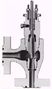
5. Features of the ring flange (below):
The ring flange is similar in shape to the flange of the flange, except that a concentric U-shaped annular groove is cut out at the convex surface. The gasket is a ring with an elliptical or octagonal cross section. The ring is embedded in the U-shaped groove and tightened. A reliable seal is obtained after the flange bolts. The ring material is usually Monel but can also be other metal. The flange still has good sealing performance under the pressure of up to 1034 kg/cm 2 (15000 psi) , but the ring flange is generally not used in high temperature applications. .
16. Welding of valve body and pipe
Features:
a. No leakage at any temperature and pressure,
b. Low connection cost (no need to prepare flange)
c. The valve body is difficult to go offline
There are two types of welded joints
a. Socket welding (SWE) is often used for valves with a nominal size of 2 inches or less.
b. Butt welding (BWE) is often used when the valve body nominal size is 2 inches or more.
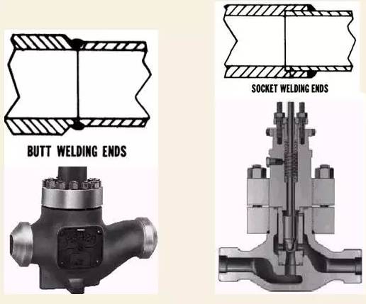
Butt welding
Seals
Seals to prevent leakage: packing and gaskets.
Two main fillers: PTFE filler, graphite filler.
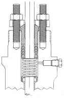
Features of PTFE packing:
(1) The friction is small without lubrication;
(2) Suitable for a variety of media;
(3) The packing ring is loaded by the spring and automatically adjusted;
(4) Working temperature -40 °C -232 °C;
(5) requires the valve stem to have a high finish;
(6) Not suitable for nuclear radiation (filling is easy to damage).
Features of graphite packing:
(1) The working temperature can be as high as 649 °C;
(2) Suitable for a variety of media and nuclear radiation occasions;
(3) Long service life;
(4) Lubrication is required when the working temperature is high;
(5) The friction is large, and it is easy to produce hysteresis (dead zone).
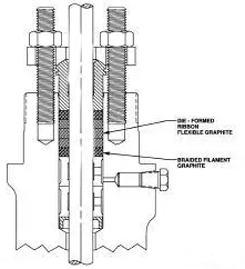
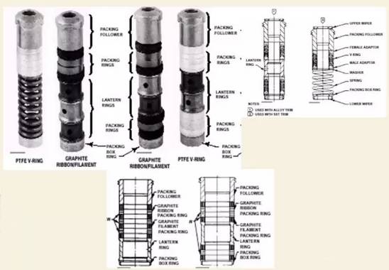
The order of installation of common fillers:
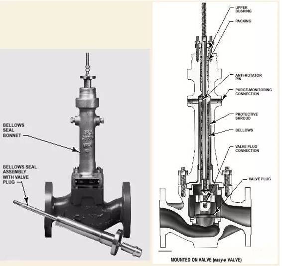
Structure and characteristics of bellows seal:
(1) good sealing performance;
(2) Long service life;
(3) Easy to install.
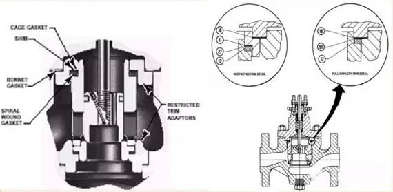
Common gaskets:
The standard gasket consists of a metal flat gasket, a metal wound gasket, and a graphite gasket.
Smart Floodlight,Smart Flood Light,Wifi Flood Lights,Smart Led Flood Light
Guangdong Smart Street Lighting Co., Ltd , https://www.fldlight.com
![<?echo $_SERVER['SERVER_NAME'];?>](/template/twentyseventeen/skin/images/header.jpg)