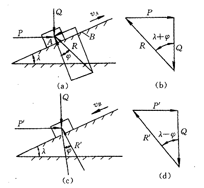
1 Characteristics of the beveled slider mechanismAs shown in Fig. 1a, the slider A is placed on a slope having a certain angle of elevation l , the friction coefficient f between the known slope and the slider and the vertical load Q applied to the slider A (including the slider itself) weight).
Therefore, in order to make this slider A not self-locking during the ascending and descending process, the following two conditions must be met:
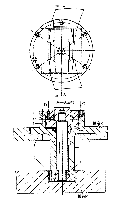
2 inclined floating clamping mechanismThe inclined floating clamping mechanism is shown in Figure 2. When the rotary table needs to be clamped and fixed, the pressure oil passes through the oil filter, the oil pump and the electromagnetic reversing valve, and then enters the oil chamber through the C port to push the piston to move. The inclined slider 5 on the piston shaft 2 is driven to move upward, and the elastic clamping body 4 is outwardly opened by a force larger than the force applied to the piston due to the action of the inclined surface, so that the clamping rail plate 6 is clamped. It is in contact with the clamping groove surface (annular groove opened on the rotary body) and is pressed to generate a pressure. Finally, the rotary table is reliably clamped by the frictional force F generated between the clamping rail plate 6 and the clamping groove surface. In order to make the clamping body smaller in volume and better in stress, the clamping body is generally symmetrically distributed on the turntable, and the arm is made larger as much as possible. We use four symmetrically arranged clamping bodies so that the central shaft is only subjected to torsional moments and the radial force is zero (Fig. 2), so that the turntable maintains high precision. When it is necessary to loosen, it is only necessary to pass a certain pressure oil to the D port, so that the piston moves downward, the ramp slider is driven to overcome the clamping resistance movement, and at the same time, due to the elasticity of the clamping elastic body 4, the clamping rail plate is clamped. Disengage from the clamping annular groove surface. In this example, the gap between the clamping rail plate and the annular groove surface of the rotating body is always maintained at about 0.1 mm (two sides) for the reliability and rapidity of the clamping action. As can be seen from the foregoing, in the bevel slider mechanism, the slider can be lifted and lowered freely while satisfying the conditions of l <( p /2)-Ø, l >Ø. Generally, we take a small coefficient of friction between the slider and the bevel, f = 0.10, then the friction angle Ø = tg -1 f = 5.246 °. In order to make the piston use a smaller driving force P, a larger clamping force Q is generated, only l > Ø, but considering the influence of other factors, here take l = 7 ° 30 ', it is clear that l + Ø<( p /2) is established to satisfy the slider self-locking condition. The clamping force Q required for the clamping body is 85 kN, and since P = Qtg ( l + Q), it is only necessary to make the driving force P generated by the piston about 20 kN to achieve clamping. Obviously, the P force is much smaller than the Q force. Compared with the conventional cylinder without clamping the slider (clamping), the cylinder volume is much smaller when the same oil pressure is required to produce the same clamping force. At the same time, the cost is low, no need for disc spring reset, saving space and making the whole mechanism smaller. Through the above analysis, it can be seen that the inclined floating clamping mechanism has many advantages compared with the traditional cylinder, and has certain generalization and practicability. For the engineering and technical personnel engaged in mechanical design, it provides a relatively novel one when doing such design work. The clamping mechanism for reference. | |||||||||||||||
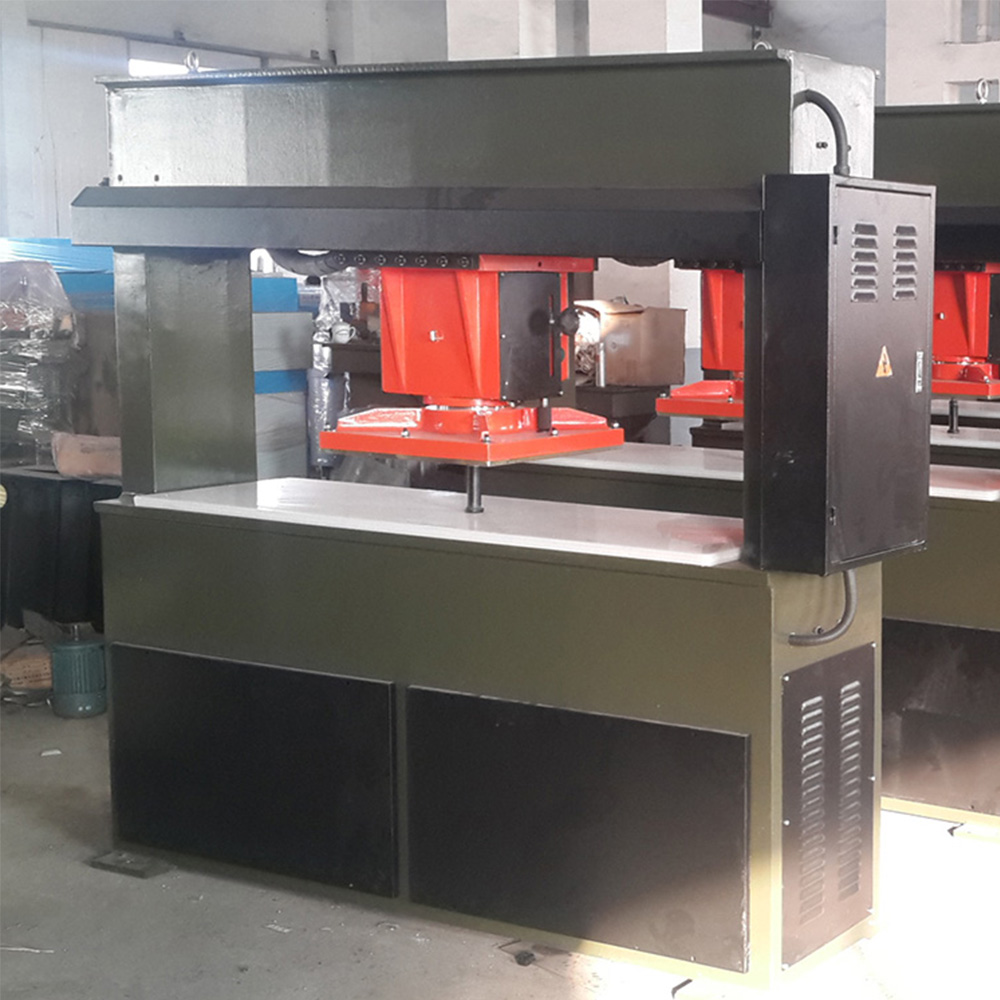
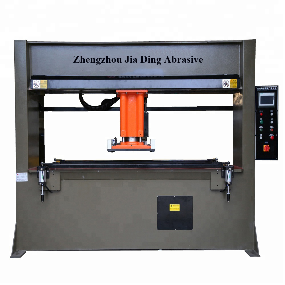
Fully Automatic Traveling Rotary Head Die Cutting Press Machine is used for the cutting of all kinds of small knife molds for leather, football panels, shoes (sole, insole, shoe-pad, upper of the shoe), cloth, masks, toys, etc.
1.The lifting position of pressing board can be freely set to reduce idle travel and enhance work efficiency.
2.The movement of cutting head is controlled by automatic speed variation to realize flexible movement with high speed and accurate positioning and without impact.
3.Differential oil way is adopted to allow rapid and convenient cutting.
4.Special specifications of the product can be customized.
Technical Info
Working pressure: 40T (other type can be customized)
Effective working width: 1650mm/ 1800mm
Punch head moving stroke: 5~150mm (up & down)
Suitable disc size: less than 400mm diameter
Punch cutting speed: 3S/punch
Can load 6 jumbo rolls with air expand shafts & automatic brake system, or simple shaft also available.
Hydraulic press, automatic movement of punch head
Equipped with automatic raw material continuous feeding system.
PLC control system, parameters like feeding length, moving height, transverse distance can be set on machine easily.
We distributes and wholesales various brands of Bonded Abrasives , Abrasive Sanding Disc, Abrasive Flap Disc , Flap Wheels , Flap Disc Backing Pad, Flap Disc Adhesive , and Surface Conditioning Product etc, and enjoy a high position among consumers.
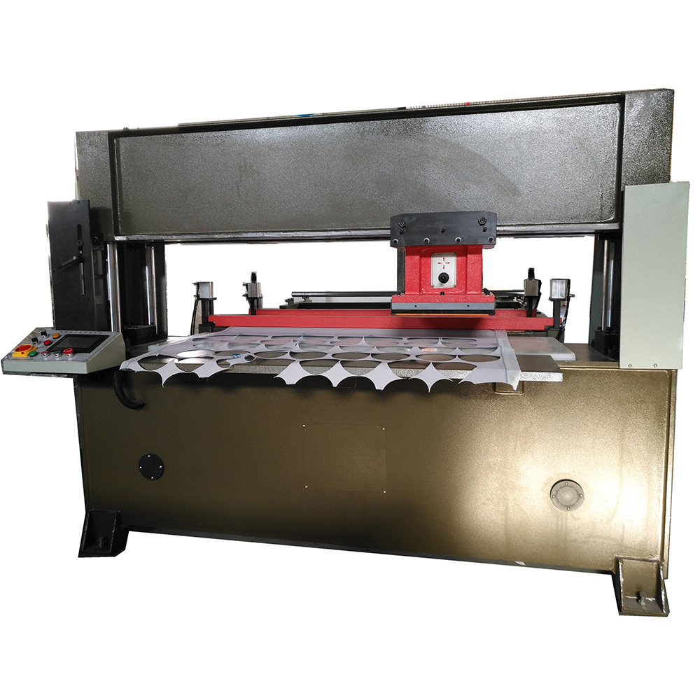
Sanding Disc Machine,Sandpaper Punching Machine,Abrasive Disc Cutting Machine,Automatic Sandpaper Machine
Zhengzhou Jiading Abrasive Manufacturing Co.,Ltd , https://www.abrasive-jd.com
![<?echo $_SERVER['SERVER_NAME'];?>](/template/twentyseventeen/skin/images/header.jpg)
