|
|
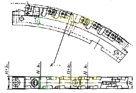
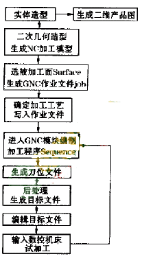
Step 4 broaching tool CAM <br> <br> structure according to the embodiment and design sketches determined, using solid modeling software entity I-deas. According to the solid shape, the three-dimensional structure shape of the finished broach can be visually previewed, and the dimensions and angles of the broach and the interference of related assembly and processing can be detected through the software measurement function, so as to verify in time. Modify and adjust the pre-design plan and generate 2D graphic design drawings at the same time.
Secondary modeling to generate a machining model unit. Each blade and its chip flute, empty knife, screws, etc. are combined into a single unit. Considering the need for sufficient feed, retraction space, feed start point, and up-cut milling in actual machining, the relevant surfaces and other reference surfaces in the independent unit are appropriately selected as the reference for the trajectory, boundary and direction of the tool. Each individual processing model unit is then generated by the object-append command.
Enter the NC-SETUP module and generate the job file jobfile. Use the surface-set command to select and determine each machining surface and reference plane of the independent unit in the quadratic geometry, and generate a GNC format job file xxx.JB.
Determine the processing technology. Due to the large diameter of the broach (Ø851mm), which exceeds the processing range of the existing machine tool, it is necessary to design a non-standard tool to clamp it on the workbench. The two sides of the machining broach must be doubled. Clamping and positioning. The process route of the single-side machining of the broaching tool is determined as: milling empty knife → rough milling insert groove → machining chip flute → semi-finishing milling insert groove → machining screw center hole → drilling screw hole → tapping → fine milling insert groove. According to the process design requirements, select the machine tool, prepare the process specification (select the tool cutting amount, machining allowance, machining route, etc.), and write the selected tool and cutting amount into the working file xxx.JB according to the GNC format.
Prepare the processing program Sequence. Enter the GNC module and load the job file xxx.JB. Programming according to the determined machining route and GNC programming commands. When programming, it is necessary to consider factors such as the direction of the cutting, the reverse milling, the forward and reverse of the tapping and retracting knife. Common programming commands are Partsurf/, Guv/, Multaxis/, Taxis/, Goto/, etc.
Generate the location file xxx.CL. After the sequence machining program is completed, the entire machining process can be simulated. After confirming that the machining route, the path of the tool, and the direction of the tool are correct, use the Finish command to end the job and generate a tool location file xxx.CL.
Post-processing. Select the special post-processing program of the machine tool to post-process the tool position file xxx.CL and generate the G program type xxx.TP that can be recognized by the machine tool. Then, according to the practical experience in CNC machining, the machining program xxx.TP is edited and arranged again to shorten the idle travel time and distance, adjust the cutting speed and so on.
Trial processing. The edited machining program is input into the machine tool for the first piece of trial machining, and the machining result is checked to match the design requirements. If the machining error is generated by the accuracy of the machine tool in the actual machining, the secondary clamping position and other factors and it is easy to adjust, it can be directly adjusted by the CNC machine operator. Otherwise, you need to return to the GNC Sequence for adjustment and correction, and perform a second trial processing until the processing result is correct.
The programming process of the indexable car broach is shown in Figure 3.
5 Conclusion The application of CAD/CAM technology has significantly improved the design and manufacturing precision and production efficiency of the indexable broach, shortened the tool production cycle and reduced the scrap rate. Through the production and application of many domestic users such as Beijing Jeep Depot, it proves that the indexable broach produced by our company has excellent performance and can replace foreign similar products.
Previous page
0.45 Um Syringe Filter,10 Micron Syringe Filter,5 Micron Syringe Filter,Syringe Filter Membrane
Dongguan Boye Instrument & Machinery Equipment Co., Ltd , https://www.boyelab.com
![<?echo $_SERVER['SERVER_NAME'];?>](/template/twentyseventeen/skin/images/header.jpg)

