![<?echo $_SERVER['SERVER_NAME'];?>](/template/twentyseventeen/skin/images/header.jpg)
In the previous CAD tutorials, we introduced some of the techniques for drawing the assembly drawings of the secondary gear reducer using Haochen CAD Machinery 2011. So, how do you draw the main view of the reducer for the secondary gear? In today's tutorial, we will actually demonstrate the rendering method.
1. Drawing the main view: First, based on the mechanical drawing basis, use the [Line] command of Haochen CAD Machinery 2011 to draw the center line of the end cap of the projection shaft and the bearing end cap from the top view (Figure 1).
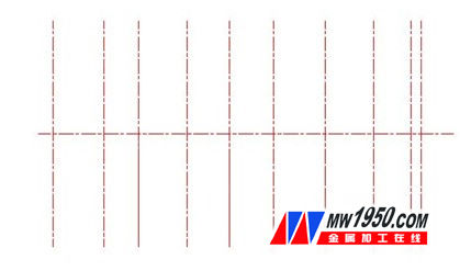
figure 1
2. Draw the main view projection of the end cap: use the [Series Circle] tool of [Drawing Tool] in Haochen CAD Machinery 2011, input the circle radius and draw the circle quickly (Figure 2).

figure 2
3. Draw the main view outline: In the drawing process, we need to use a lot of commands such as circle, arc, line, mirror, offset, and trim. Here, in order to improve efficiency, we use the shortcut key command in Haochen CAD Machinery 2011. Because Haochen CAD mechanical software supports visual shortcut command modification, we can customize the commands that need to be reused in CAD drawing. For the shortcut keys that are commonly used by you, the operation is greatly simplified (Figure 3).
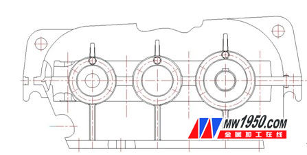
image 3
* Plate FLANGE (Plate Flange, Flat Flange, Plain Flange)
* SLIP ON FLANGE (SORF SOFF FLANGE)
* WELDING NECK FLANGE (WNRF FLANGE)
* BLANK FLANGE (BLIND FLANGE, BLFF FLANGE, BLRF FLANGE)
* THREADED FLANGE (SCREWED FLANGE)
*BACKING RING FLANGE
Blank Flanges,BS4504 Blank Flange,DIN 2527 Blank Flanges,Steel Blank Flanges
Shandong Zhongnuo Heavy Industry Co.,Ltd. , https://www.zhongnuoflanges.com