![<?echo $_SERVER['SERVER_NAME'];?>](/template/twentyseventeen/skin/images/header.jpg)
The product modeling process based on digital image features is shown in Figure 2. First, according to the eye tracking sketch function provided by PRO/E, some important points are obtained. They have graphical feature information, then curve through these points, then construct the surface through the curve, and finally generate the entity. The design idea is point → line → face → entity. The design steps are:
(1) After entering the PRO/E environment, first create a "part" (.PRT) file.
(2) Open the drop-down menu Insert-Style to enter the styling feature, then click on Trace Sketch to track the sketching function. Three options are visible in the Trace Sketch dialog, three different views, which indicates that ProlE can provide outline information for the image from at least three views. Select the Front face as the bottom surface and select the desired image to lay on the bottom surface for drawing. To make the picture clearer, you can set Translate to zero in the Properties bar. There is a yellow money on each side of the picture. You can choose the size of the image size you want by moving the money. You can also adjust the height of the upper and lower areas. When the position of the picture is adjusted, we will start the outline of the dragon in Figure 1. Lines are drawn.
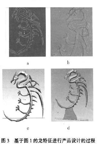
(3) Click on the Front face as the datum surface, and the mesh will appear on this face, which means that the face is the active plane. Re-select the Plannar in the lower left corner to start drawing the plane curve. In order to make the prototype more accurate, you can enlarge the image. Select a number of points along the outline of the graph and connect the points through the curve to get the approximate outline of the desired graph. At the same time, it is worth noting that in order to get a good quality curve, the number of points is taken as little as possible. The command is Set the active datumplane-Fronr-Create Cures-Planar. When the outline is drawn, if you are not satisfied with some of them, you can edit the curve with Curve edit and modify it with the curvature map until you are satisfied. The extracted and modified characteristic curve is shown in Figure 3a.
(4) Because the contour curve is still a flat figure, and a 3D solid model is needed for product manufacturing, this feature curve needs to be three-dimensionally materialized according to the product design needs. First make a datum plane parallel to the Front face. If the spacing between the two faces is appropriate, select the desired feature curve segment and project it onto the newly created datum. The operation is as follows: Point drop curve A little extension surface (ie Front surface) A surface just created (ie DTMI) - Select DTMI to be a little down in the direction of the drop to complete the drop curve. In order to construct the entity with a small number of small surfaces, it is also necessary to add a spatial curve between the FRONT surface and the contour drawn on the DTMI surface in combination with the information of the picture, and connect the contour lines on the two surfaces to form a closed interval. In order to build a surface. As shown in Figure 3b. In ISDX, four or three spatial (or planar) curves can be used to construct surfaces, Stying-Swface-Boundary Curves, or a middle curve (Seconday) to make the surface more compliant. In order to ensure the quality of the two connected surfaces, the connection between the connected surfaces is divided into three levels, namely GO, G1, and G2.GO, which will make the sharp edges of the graphics continuously, and should be avoided as much as possible; Gl means that the faces are tangent and continuous. That is, the first-order continuous, usually the face is drawn; G2 means that the curvature of the adjacent faces is continuous, that is, the second-order continuous, which is difficult to achieve. After the surface is built in turn, all the surfaces need to be merged. The command used for merging is Insert-Merge. You can combine two or more faces into one face at a time, and repeat this process until you finally compose a complete face. At this point, half of the surface is constructed. Figure 3c shows the merged surface.
(5) The model designed in this paper is about the surface symmetry of the Front, and then it is transformed into a symmetrical closed 3D surface by mirroring. Use edit - Mirror to select the Front face as a symmetry plane. After the mirroring, the original surface and the mirrored surface must be merged into one surface by the Merge command to pave the way for the subsequent materialization. The construction of this surface is complete. Use the Edit - solidity - Protrusion-OK to generate a 3D solid model.
(6) The corners of the 3D model are smoothed by rounding, and the bottom support and eye parts can be made with a stretch command.
(7) According to our product design requirements, we finally add the base, text and icons to the Lanwei CAD model. That design concept is derived from the digital picture features, and the product design is completely completed according to the requirements of the new design, as shown in Figure 3d.
2 SLA Prototype Rapid Manufacturing Process
The SLA method is currently the most widely used process in the field of rapid prototyping technology, and has the advantages of high precision of prototype and fast manufacturing speed. This topic uses this method to make a rapid prototype of the design of the previous section. SLA technology works on the principle of photopolymerization of liquid photosensitive resins. At a certain wavelength (such as λ = 325 nm) and intensity of ultraviolet light, the photosensitive resin material can rapidly undergo photopolymerization, and the material changes from a liquid state to a solid state, and layers are stacked to form a rapid prototype. The SLA molding equipment adopts Xi'an Jiaotong University light curing rapid prototyping machine (Model: SPS450). The equipment consists of laser scanning system, pallet lifting system, resin circulation system and coating system, temperature control system and computer control system.
First, the CAD model of the designed dragon modeling crafts is output in Pro/E as STL format. Since the STL file cannot be used directly by the molding machine, it must be converted into the contour information of the 2D lamination part, so the 3D part needs to be layered and sliced ​​by the data processing software. The data processing software uses RPData developed by Xi'an Jiaotong University. The current model is layered in RPData with a layer thickness of 0.1 mm.
Rapid prototyping is the process of transferring manufacturing data to a molding machine to quickly form parts, which is at the heart of rapid prototyping. The process parameters are generally changed depending on the characteristics of the part to be made, the state of the equipment, and the condition of the part being made. The characteristics of the parts mainly consider the maximum height of the parts, the size of the cross-sectional area, and the amount of support plus; the state of the equipment mainly considers the light intensity. The process parameters are modified based on the conditions of the parts that have been cured, the boundaries, the corners, and the magnitude of the error. The main process parameters used in this study are: laser scanning power 190 MW, base height 8 mm, thickness 0.1 mm per layer, filling scanning speed 4 600 mm/s, support scanning speed 1600 mm/s, jump speed 10 000 mm/s, contour The scanning speed is 3500 mm/s, the compensation diameter is 0.16 nun, and the table lifting speed is 2 mm.
After the part is created, the computer will prompt you to remove the finished part. First, lift the work surface out of the liquid level and then shovel it out with a shovel. After the parts were taken out, they were washed with an ethanol solution to remove the support. After the cleaning is completed, it can be post-cured. Place the part under UV light for about 15 minutes. Prototypes generally also need to be polished to get a good look. The prototype of the finished dragon modeling SLA is shown in Figure 4.

Previous page next page
Flame Retardant Extruded Board
Yu Ou Nuo XPS Extruded Polystyrene is a new type of building material widely promoted and used in my country. This new type of environmental protection material that uses waste plastics to turn waste into treasure. Due to its excellent high strength, compression resistance, and excellent heat preservation, heat insulation, light texture, convenient use, high-quality hydrophobicity, damp-proofing and environmental protection performance, good stability and corrosion resistance, it has become a new type of building material widely promoted in the construction industry. Xps Foam Board Heat Insulation is widely used for wall and floor insulation.
Flame Retardant Insulation Extruded Board,Fire Prevention Extruded Insulation Board,Fireproof Extruded Board,Flame Retardant Foam Board
Zhengzhou Ou Nuo Building Materials Co., Ltd. , https://www.yuounuo.com